Define the component and machine boundaries
A slip ring is part of the machine’s electrical and mechanical architecture. Its validation cannot be completed by reviewing a product sheet alone. Define the stationary supply, rotating loads, protective measures, cable system, control equipment and mechanical interfaces that form the complete installation.
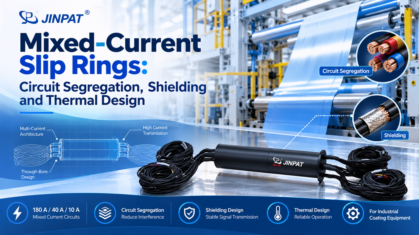
The source configuration was developed for coating machinery and combines eight 180 A circuits, sixteen 40 A circuits and ten 10 A circuits. It is documented for up to 440 V and uses a 50 mm through bore. These values are inputs to the engineering review, not proof of suitability for a different machine.
Create a requirements-to-evidence matrix
List every requirement with its source, acceptance criterion, verification method and evidence owner. Requirements should cover circuit count, continuous current, peak duty, voltage, insulation, terminals, protective earth, dimensions, speed, environment, service access and documentation.
The matrix should identify whether evidence comes from design review, supplier declaration, inspection, calculation or test. Open items remain visible until they are resolved. This is especially important for custom assemblies whose abbreviated model code does not reveal the complete specification.
Electrical and insulation verification
Confirm the circuit schedule against the wiring diagram and released drawing. Review creepage, clearance and insulation materials using the standards applicable to the complete machine. Define insulation-resistance and dielectric tests with the correct voltage, duration and pass criteria. Verify terminal identification and protective-earth continuity where applicable.
Temperature and load verification
Develop a representative load profile that includes simultaneous loading. Measure temperature rise at selected terminals, conductors and housing locations after stable conditions are reached. Peak-current claims need a separate duty definition. Do not publish or accept a peak value without duration, repetition rate and thermal limits.
EMC and shielding verification
The source record states that each current group is separately shielded. Review the complete bonding and grounding concept, including external cables and connected drives. Component construction can support EMC performance, but the machine builder must verify the complete system under representative operating modes.
Validate the mechanical interface
Check the approximately 200 mm outside diameter, 873 mm length and 50 mm bore against the controlled machine model. Review tolerances, runout, mounting stiffness, anti-rotation arrangement, cable bend radius and replacement access. Confirm that the mating shaft or pipe cannot touch the bore during operation or assembly.
A rotation test should monitor mechanical behavior as well as electrical continuity. External cable forces and misalignment can create problems that do not appear in a stationary bench test.
Prepare the technical documentation
Retain the approved drawing, circuit schedule, supplier test reports, material or conformity documents required by the project, risk-assessment inputs and deviation approvals. Use revision-controlled identifiers. The public website should hide the exact project code, while the technical file must preserve the exact installed configuration.
A slip ring by itself does not make the complete machine CE-compliant. The machine manufacturer remains responsible for the conformity assessment, integration risks and applicable EU requirements.
Make release conditional on closed evidence
Release should follow the requirements matrix, not a general statement that the component is ‘industrial grade.’ Close critical deviations or document the accepted mitigation. If the application changes, reassess the affected requirements instead of assuming the earlier evidence still applies.
This evidence-led process supports safer publication too: only claims with traceable engineering support should move from the internal file to public marketing copy.